Principle of High Voltage Interlock Loop and Troubleshooting
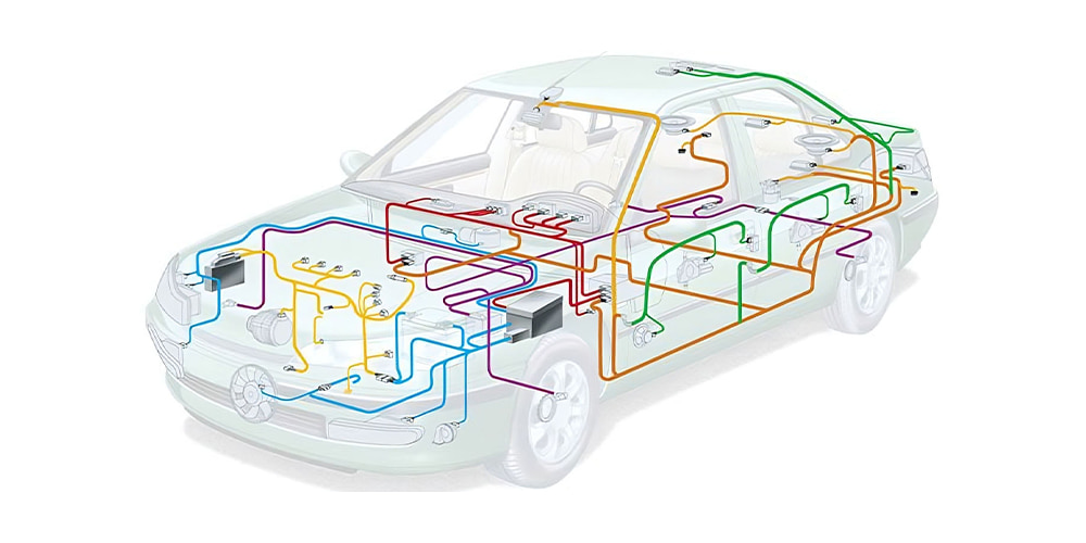
There is no doubt that new energy vehicles are one of the popular development directions in the passenger car field at present. New energy vehicles are significantly different from traditional fuel vehicles. In particular, pure electric vehicles will not be able to perceive their working condition and judge the safety status of the vehicle through obvious shaking, smell, heat and other ways like fuel vehicles. Therefore, other approaches are needed to ensure the safety and reliability of the vehicle during operation. High-voltage insulation detection and high-voltage interlock loop are essential technical solutions.
At the same time, in order to ensure that the high-voltage harness of each appliance is connected in place to prevent accidental contact with leakage (equivalent to fuel leakage). In order to ensure safety in abnormal conditions (e.g. collision damage, disconnection of high voltage appliances by abnormal operation, etc.), inspection and visual inspection alone are not sufficient. Therefore, the high voltage interlock circuit is extremely important. The article introduces the principle of high voltage interlock circuit and troubleshooting ideas based on the common fault cases.
1. Principle and Structure of High Voltage Interlock
1.1 Basic Principle
A closed circuit is formed with the help of an ECU and a low-voltage harness. The ECU checks the integrity of the circuit. If there is a short circuit or open circuit in the circuit, it is considered a potential danger and the high voltage output is prohibited.
As shown in the figure below, the BMS is responsible for sending and receiving the PWM waveform. Under normal conditions, the waveform passes through the PTC, PDU, and EAC electric compressor modules before reaching the BMS, which checks the received signal parameters to determine the circuit integrity and indirectly reflects the high and low voltage harness connection status and module operating status.
If the BMS does not receive the inspection waveform, there may be direct and potential hazards such as uninstalled high voltage cables (exposed high voltage cables), damaged high voltage components, and failed protective structures. This solution can detect the fault even if the interlock circuit is broken resulting in a short or open circuit to electricity or ground because of the PWM waveform. This avoids the situation of unrecognizable high-voltage electrical exposure due to a low-voltage harness circuit failure and is safer.
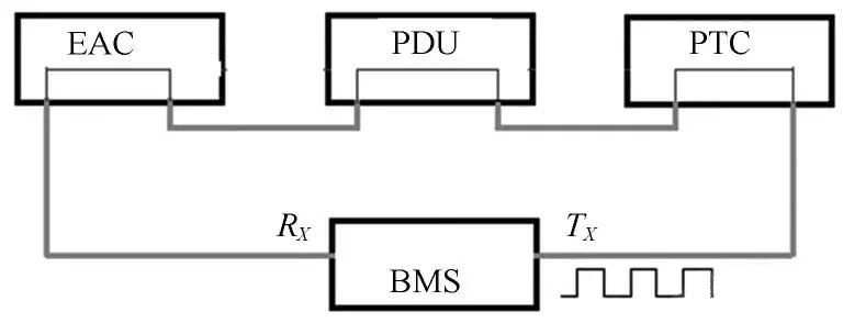

The solution can be one loop or several loops relatively independent of each other. The advantage of several circuits is that the point of failure can be quickly locked. It is also possible to selectively disconnect the isolated high voltage according to the fault situation to meet the basic customer needs of the vehicle.
In contrast to such a travel loop scheme, there are simpler ways of implementation, such as single-wire system. That is, the A controller gives a voltage or PWM signal, after a series of high-voltage components by the B controller to accept detection.
However, from a safety point of view, the use of PWM signals is certainly a very good choice to avoid interlocking loops to ground or short-circuiting to electricity.
1.2 Main Structure of High Voltage Interlock
The vehicle high-voltage system mainly involves energy storage output unit (power battery), power distribution unit (PDU) and electrical appliances (such as motor inverter, electric compressor, high-voltage PTC, etc.).
Looking at the structure of various high-voltage appliances and high-voltage components, there are two main possibilities for personal injury caused by high-voltage exposure:
- Various covers or end caps do not cover the high-voltage wiring harness, resulting in exposed voltage;
- The high-voltage wiring harness is not connected to the quick interface, resulting in exposed high voltage. Therefore, the main design goal of the high-voltage interlock is to avoid the above two possibilities.
The diagram below shows a PDU cover interlock schematic. After the high voltage harness is connected, it will connect the interlock circuit. The cover plate is assembled with the switch closed, which eventually makes the interlock circuit closed. Whether the high-voltage harness is not connected or the cover plate is not covered, it will make the high-voltage interlock circuit open and not allow high-voltage output, so as to avoid the risk of electric shock caused by high-voltage exposure.
There are various forms of interlock switches, either lever type or push button type, each with its own advantages and disadvantages. The basic principle is that the cover or end cap is designed with a tab or rib, and after the cover is pressed the switch will close its switch, making the interlock circuit closed and having the necessary conditions for high voltage on.
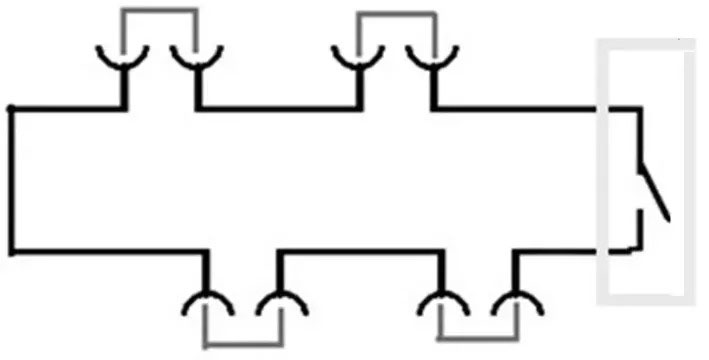

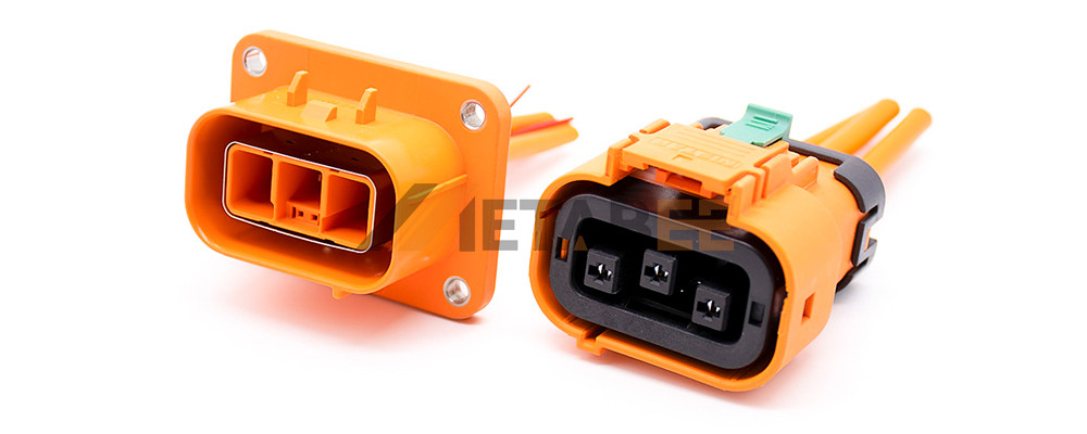
The principle of the above diagram focuses on the linkage of the high voltage harness to the low voltage interlock circuit. In the diagram below, the male interface is fixed to the consumer or PDU with the female terminal of the interlocking circuit, which is connected in series in the low-voltage interlocking circuit. The female end connector is the harness end with the interlocking male terminal integrated. The male terminal is shorted together, and only if the harness is well connected, it is possible to make the interlock circuit closed and finally have the necessary conditions for high voltage electrical output.

2. High-voltage Interlock Common Faults and Troubleshooting
As a circuit, the fault is nothing but open circuit and short circuit. The following is an example of a specific case to introduce common open circuit and short circuit situations.
2.1 Open Circuit Due to Wiring Harness Error
In the manufacturing chain, given that the production of wiring harness still relies on manual assembly, it is inevitable that wiring harness errors occur. Wire harness quality inspection can be gated with the help of an electrical inspection table. However, in the engineering development stage, the harness is often improvised or hand-made, and errors are inevitable.
From Figure 1 and the description of the basic principle, it can be seen that only the two PIN pins of the BMS are not directly connected together in the whole circuit. Therefore, if the other appliances are well connected to the harness, the conductivity should be measured from the 2 PIN pins of the BMS harness. In the process of troubleshooting, first from the ECU 2 PIN pin corresponding to the wiring harness conduction, to confirm the circuit does not pass, use the "dichotomy" to investigate.
Take Figure 1 as an example, from one PIN pin of the BMS corresponding harness, measure to the PIN pin corresponding to the PDU (the actual choice is often convenient to operate the unit or module), across several modules. If it fails to conduct, the scope of the fault is quickly reduced by half. Next, continue to narrow down the scope from the side of the BMS where the fault is located, and eventually pinpoint the location of the open circuit.
If the low-voltage harness is on, then you can consider an electrical fault. For example, the interlock switch of the PDU is not working, the interlock terminal of the high voltage harness is damaged, or the circuit is shorted to ground or to electricity.


2.2 Interlock Switch Failure Leading to Open Circuit
A common failure of the interlock switch is that the switch does not close after the cover is closed. Two types of problems occurred during the prototype test production:
- Deviations in the design dimensions caused the interlock switch to fail to close;
- The protruding rib structure of the cover plate was low in height, causing the switch to fail to close in place and the interlock circuit to open.
The interlock switch structure failed during installation due to unreasonable design, resulting in the switch not closing. The reason for this example was that the interlock switch was facing in the opposite direction of some assembly technicians moving the cover plate. In order to install it in place, the assembler pushed the cover plate so hard that it bent the interlocking tabs.
This indirectly indicates that the design of the interlock switch needs to take into account several possibilities for installation, adjusting the orientation of the switch, etc., to avoid structural failure. In addition there are cases where the switch itself fails to close due to a failure of the switch.
2.3 Open Circuit Caused by Receding Terminal Pins
Pin-out includes terminal quality problems in some of the low-voltage harnesses of interlocking circuits, as well as in high-voltage appliances and PDUs on high-voltage interlocking circuits.
The figure below shows an example of a retired terminal. If the male and female terminals have poor contact due to receding pins or other quality problems, you also need to use the "dichotomy" method to quickly locate the fault location. After locating the fault point, if there is no problem with the wiring harness conduction, the cause of the fault is in the high-voltage components.
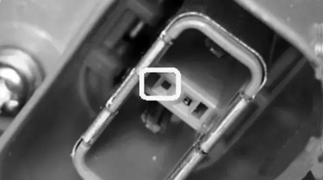

The problem of ejected pins and poor terminal contact indicates the need to use a suitable probe when performing problem identification and conduction. If the probe diameter is large, it will affect the contact quality and life of the terminal.
2.4 Short Circuit to Ground/Power
The fundamentals section describes how the ECU determines the integrity of the high-voltage interlock by sending a rectangular waveform from the ECU and then checking to see if the waveform can be returned.
If there is a short to ground or a short to the power supply in the high voltage interlock circuit, it is obvious that the PWM waveform cannot be returned to the ECU, which will cause the ECU to report a high voltage interlock fault and thus prevent the high voltage from being applied.


2.5 Power Cell Internal Fault
As shown in Figure 1, the power cell emits a square wave internally and detects the square wave. If the whole vehicle reported a fault in the high-voltage interlock circuit, and the actual conduction down the harness is intact, and there is no short circuit to electricity or ground, then you can continue to investigate to verify whether the fault is internal to the power cell.
The method is to measure the interlock circuit with power whether the formation of the path. That is, to confirm that the low-voltage harness circuit is connected, the high-voltage harness are connected intact. Then disconnect any part of the high voltage interlock circuit and use the ohm gear to measure if it is conducting, if it is not conducting, it means no current is flowing. Next you can check if there is a square wave of voltage and if the male terminal receiving the square wave is good.
3. Conclusion
High-voltage interlocks are essential to ensure user safety and safe vehicle operation. However, in the production and after-sales maintenance process, the high-voltage interlock circuit inevitably fails. In this paper, through the analysis of high voltage interlock principle, structure and major faults, we can get the basic ideas and practices of high voltage interlock fault finding.
With the rapid development of automotive technology, interlocking circuits will develop in the direction of more reasonable, intelligent and standardized, forming a multi-loop, local control pattern. Not only is it convenient for inspection and maintenance, but also can meet the needs of customers under a variety of working conditions.

